 |
|
|
|
Simulation of Sidescan Transducer
Arrays
|
Page: 1, 2, 3
|
A
sidescan sonar
ranks among the most desired tools of those dealing with the
investigation of the seafloor, for instance for diveground-prospection
or
shipwreck-hunting, but unless you do this professionally the prices of
this kind of equipment are out of reach. Without doubt a sidescan sonar
is a
precision instrument, but on the other hand the basics are long known.
So there are a handful of amateurs
around the world that build
their own sidescan sonars, some do it in a really professional way, and
some go the easier but nevertheless promising way of using an array of
fishfinder or depthsounder transducers to build a sidescan sonar
transducer.
Nowadays you can get very nice readout electronics for
fishfinders at reasonable prices, so the most important question is
what can be expected from such transducer arrays compared to
professional sidescan transducers. I ran some simulations to find an
answer and to see if the fishfinder transducer arrays can be optimized. |
|
|
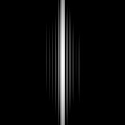
The
first
simulation (Fig.1b) shows what we would like to have:
the theoretical sound-pattern of a nearly perfect sidescan transducer
array working at 50kHz. The calculated array is 610mm long,
consisting of 6 inividual piezo-elements measuring 100mm x 25mm at
the side facing the water, the elements are spaced at 2mm (Fig. 1a).
|
|
 |
| Figure
1a:
Sidescan Sonar Transducer Array, 610mm x 25mm |
|
|
 |
Figure 1b:
polar plot for the calculated horizontal energy distribution
of the sidescan transducer in Fig.1a working at 50kHz.
89% of the
emitted energy is concentrated in the central lobe.
|
|
The horizontal
beamwidth is determined by the length of the transducer
(610mm), the vertical beamwidth (not visible in the plot of Fig.1b) by
the transducer hight (25mm).
Another kind of plot is also very instructive:
Fig.1c shows the
two-dimensional soundfield of the transducer that is projected into the
water as a grayscale image as seen from the position of the transducer.
|
 |
Figure
1c: 2-D projected soundfield of the transducer in Fig.1a Fieldsize:
120° horizontally (azimuth) x 120° vertically (hight)
|
|
|
|
|
The
second simulation (Figures 2b and 2c) shows what we have when we use a
fishfinder transducer with a single 44mm circular piezo crystal (Fig.
2a). A
very broad circular beampattern is sent away from the transducer.
|
 |
Figure
2a: geometry of the sound projecting plane of a single fishfinder
transducer
|
|
|
|
 |
Figure 2b:
polar plot for a single fishfinder transducer (Fig.2a) working at
50kHz.
|
|
|
 |
Figure
1c: 2-D projected soundfield of a single 44mm fishfinder transducer at
50kHz. Fieldsize:
120° x 120°
|
|
|
|
The
good resolution
of a sidescan sonar among other things is due to a small central lobe,
so we want a long transducer. It is clear that a single fishfinder
transducer will never draw a detailed reproduction of the seafloor. The
idea when working with fishfinder or depthsounder transducers is to set
them up in a row to imitate a long transducer. How will the beampattern
of such a setup look like and can it be optimised?
|
Next Page
|
|